Introduction
Permeability is a measure of the ease of a fluid that passes through the filter medium. It is one of the important properties for nonwoven filter media. Air permeability of a nonwoven filter media is the measured air flow through an area of filter media at a specified pressure drop. The most popular way of measuring air permeability is to fix the pressure drop and measure the airflow1. The air is sucked through a clamped medium specimen into an enclosed chamber and out through an orifice. Manometer across the medium gives the pressure drop and manometer across orifice gives pressure drop across the orifice for calculation of airflow. Data tables are provided to convert pressure drop into airflow values. The airflow measured is based on Darcy’s Law:
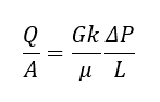
Q is the volumetric flow rate, A is area of the medium, μ is the air viscosity, ΔP is the pressure drop , L is the thickness of the filter media and k is called as permeability constant. G is a shape factor that corrects for converging flow geometry for thick filter media.
Procedure3
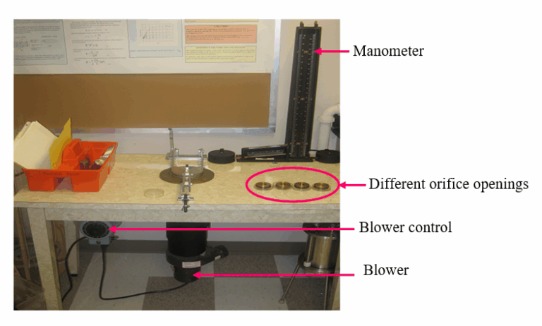
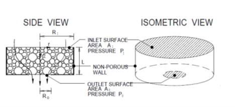
The test set-up is shown in figure 1.The filter to be tested is fit closely in the sample holder to avoid any air flow along the sides of the sample. Air flow along the sides of the medium will produce incorrect results because air is not flowing through the medium. Different orifice openings are tested and specific orifice opening is selected to obtain the pressure drop at 0.5 psig as the test is designed to produce accurate result at 0.5 psig pressure drop. The Frazier test is designed for thin samples where the shape factor is 1. For thick filter samples, the shape factor is obtained from a correlation shown in figures 3 and 4 which is incorporated in the permeability calculations.
First shape factor is determined for the given medium. It is obtained by solving equation

For given geometry the equation can be rewritten as
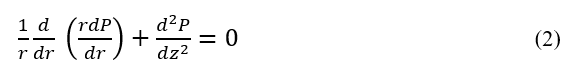
The boundary conditions are:
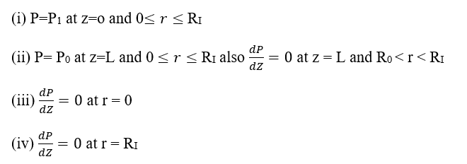
These boundary conditions are consistent with Darcy’s law which requires a zero pressure gradient in the direction of zero flow. (i) and (ii) tell that pressure at inlet and outlet surfaces are uniform and constant. Third boundary condition is at an axis of symmetry (r = 0). Fourth boundary condition assumes no flow at the impermeable surface on the outside of the disk. A finite difference numerical approach is applied to solve above mentioned equation as separation of variable method is not applicable due to compound boundary condition z = L. The total flow rate through the outlet surface is obtained by numerically integrating the local velocity across the surface and shape factor for disk (Gdisk ) is found:
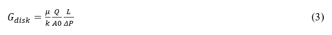
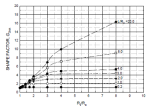
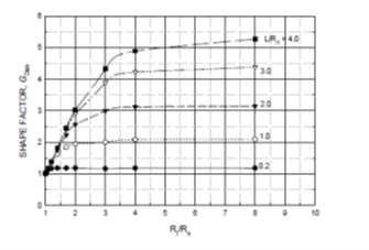
Gdisk is calculated by plotting varying the ratios of L/Ro and RI/Ro. Figure 3 shows the plot for the same. This figure shows a dependence on L and RI for a fixed value of Ro. For L/ Ro of 2 or less Gdisk approaches asymptotic value. For values of L/ Ro greater than 2 Gdisk varies very linearly with RI/ Ro. This leads to conclude that for thin disks and large values of RI/ Ro the outer part of the disk far from the exit surface does not contribute to the total flow. For very thick disks the flow field depends more on the depth, L.