Foam Hydrocarbon Traps in Automotive Air Induction Systems

Air pollution from automotives presents a serious problem and needs to be controlled. It is widely accepted that, in urban settings, 45% of VOC pollutants are emitted from motor vehicles [1]. CARB estimates that over 90% of Californians inhale unhealthy air at some period during the year [2].
Automobile manufacturers have done an effective job in reducing the amount of emissions being released into the environment. One possible escape path for engine-born VOC’s is through the Air induction system (AIS), when the engine is hot and not operating (keyed off). The VOC’s originate from unburned fuel present in the manifold and from other sources, which diffuse out of the AIS into the atmosphere. The temperature difference between the hot engine and relatively cooler environment drives the diffusion process. In order to meet the new LEV II and PZEV emissions requirement (developed for the full vehicle) the VOC’s egression from the engine need to be controlled.
New technologies (HCA) have been developed, and marketed, to reduce the amount of VOC’s that are allowed to exit this system. Many of these technologies function by adsorbing the VOC’s onto the surface of a device, temporarily trapping the molecules. Once the engine is started, the engine air flow creates a differential that pulls (purging) the VOC’s back into vapor phase. The purged VOC’s are eventually burnt in the combustion chamber. Some of these new technologies make use of activated carbon coated foams. The open-cell reticulated foam structure is effectively used to coat the activated carbon. The activated carbon is specially formulated to trap and release VOC’s as desired.
Design Challenges
One of the challenges in programming an air induction based HCA is defining the emissions control aspects of its function. This is governed by three basic factors:
- HCA Capacity: Concentration, of VOC’s the HCA is expected to encounter during normal operation?
- HCA Efficiency: Efficiency of the HCA to ensure that the vehicle will meet emissions control specifications?
- HCA Purge Rate: How quickly should the HCA purge VOC’s back into the air induction flow stream once the engine starts operating?
Some key design attributes for a HCA device in the AIS are;
- No system pressure loss increase.
- No Leakage
- 150K miles functional durability requirement.
- No engine performance degradation over 150K miles 10+ years.
- No serviceability recommended.
- High capture efficiency under all conditions.
- Desired working capacity to meet engine emissions.
- HCA device should not dissociate, nor be ingested into the engine during typical driving conditions.
- Full purge of hydrocarbons on EPA evaporative drive cycle after HCA has been loaded to working capacity.
- HCA device must be either fully separable from AIS or a separate device altogether.
- HCA device preferable will be on the clean side protected from dust, water, snow, salt, soot etc.
Foam HCA
Most hydrocarbon traps in automotive engine induction systems utilize activated carbon as an adsorbent media. Activated carbon is relatively inexpensive and is very effective at trapping hydrocarbon molecules via an adsorptive mechanism. One of the key factors that gives activated carbon its ability to adsorb VOC vapors is the vast amount of surface area available due to its incredible porous microstructure (please see previous one minute filtration article in Jan 09). It has been estimated that 1-kilogram of activated carbon contains a surface area of 1,000 square kilometers [3, 4, 5].
Extending the idea of maximizing surface area to optimize adsorption, a hydrocarbon trap utilizing foam in a sandwich structure has been developed (figures 1 and 3). The core of this trap is composed of large cell reticulated foam coated with activated carbon. This design not only features a robust and effective adsorptive capacity per unit volume, it also allows for a more complete purge of vapor during engine operation due to the open structure of the foam. In addition to its optimal performance, there are a variety of packaging options for this material. It can be designed as a stand-alone HCA as shown in figure 1. The HCA can also be designed into a long life filter design [6] as shown in figure 2.
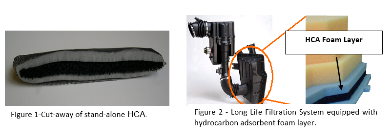
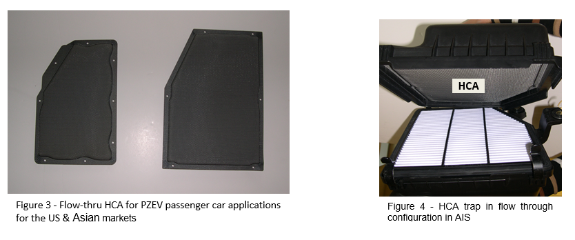
Figure 3 shows another view of a full HCA device that was installed in the engine air cleaner. Figure 4 shows the same device as installed in the engine air cleaner.
References
- S. Environmental Protection Agency, Sources of Pollutants in Ambient Air, Air Pollution Control Orientation Course, http://www.epa.gov/apti/course422/ap3a.html.
- California Air Resource Board, Health and Air Pollution, 28 March 2006, http://www.arb.ca.gov/research/health/health.htm.
- Development of Evaporative Emissions Filters for Automotive Applications, J.M. Leffel and G.S. Green, American Filtration and Separations Society Conference, Reno, Nevada, June 17-20, 2003.
- Jeffry M. Leffel and Reza Abdolhosseini, PhD, ‘Requirements Setting, Optimization and “Best Fit” Application of AIS Hydrocarbon Adsorption Devices for Engine Evaporative Emissions Breathing Loss Control”, SAE technical paper #2005-01-1104, presented in Detroit 2005.
- Schaffer S, Arruda A., Bielicki J. And Bugli N., ‘Design Considerations and Characterization Test Method for Activated Carbon Foam Hydrocarbon Traps in Automotive air Induction Systems’, Paper presented at the 2007 SAE Conference and Expo, #07PFL-913, Detroit, MI.
- Bugli N. J and Green G. S, “Performance and Benefits of Zero Maintenance Air Induction Systems”, SAE technical paper 2005-01-1139.
Nomenclature: AIS=Air Induction Systems, HCA=Hydrocarbon Adsorber, VOC=volatile organic compounds, LEV=low emission vehicles, PZEV=partial zero evaporative vehicle, CARB=California Air Resource Board.
Tags
